
ENGINEERING APPLICATION CASE · WIRE & CABLE
Cable Extrusion Line Meter Marking with CIJ and Encoder Synchronization
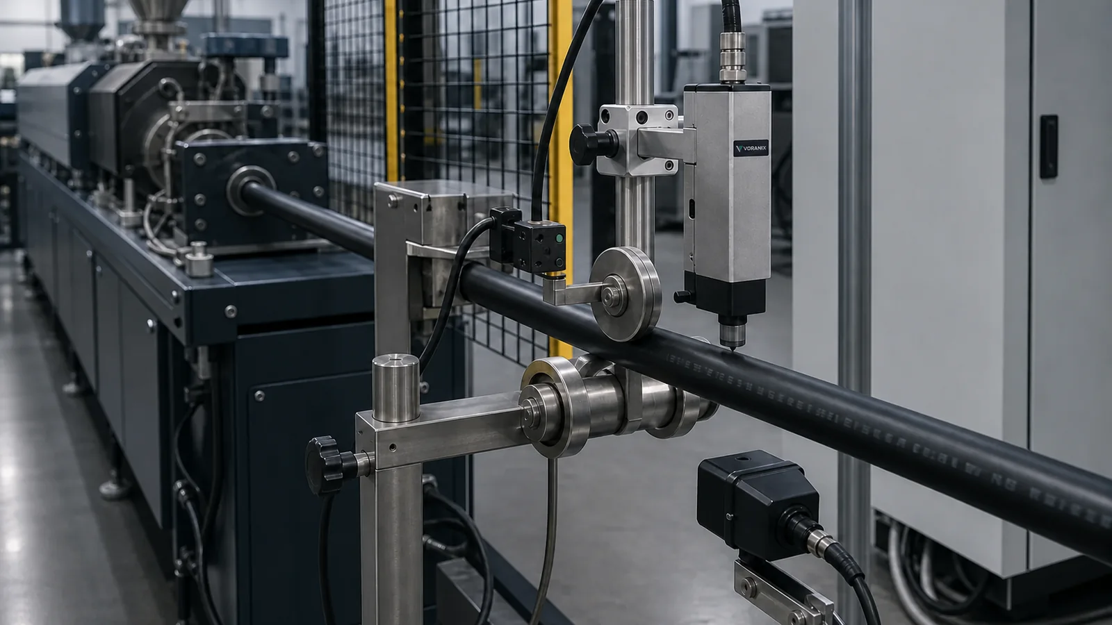
Continuous cable must be coded without contact while line speed, surface temperature and vibration change. This concept combines CIJ printing, encoder-based distance tracking and optional downstream inspection.
PRODUCTION CHALLENGE
What the process must control
An encoder can measure line movement, but wheel slip, cable vibration and start-stop behaviour can introduce distance errors. Freshly extruded surfaces may be warm or contaminated, and black cable requires a compatible contrasting ink. The design must define where distance originates, when counting resets and how scrap or restart lengths are handled.
PRODUCT, PACKAGING & SUBSTRATE
Inputs required before equipment selection
- Confirm jacket polymer, colour, surface temperature, diameter range and additives.
- Provide normal and maximum line speed, acceleration, stopping behaviour and vibration range.
- Define metre interval, text, direction, repeat length, batch source and reset rules.
- Identify adhesion, abrasion, chemical, weathering and readability tests for the finished cable.
ACCEPTANCE CONDITIONS
Define success before trials
- Print adhesion and contrast meet the approved test on the real jacket material
- Metre marks remain within the agreed distance tolerance under defined line conditions
- Text position and orientation remain readable over the diameter range
- Start, stop, restart, scrap and counter-reset behaviour follow the line specification
A / B / C SOLUTION PATH
Choose the required control level
The recommended level is provisional. A VORANIX engineer must review samples, code data, line conditions, inspection criteria and system boundaries before quotation.
A. Synchronized CIJ coding
CIJ printer, printhead bracket, suitable ink, encoder, counter logic and operator message selection.
Discuss this option → Recommended provisional levelB. Print and inspect
Add cable stabilisation, controlled lighting, camera and alarms for presence or legibility faults.
Discuss this option →C. Production-data integration
Add recipe download, lot data, length records, event logging and scoped extrusion-line or MES interfaces.
Discuss this option →PROVISIONAL CONFIGURATION
Recommended engineering concept
For the stated risk profile, begin with a mark-or-print and verify concept, then add traceability functions only where the data owner and recovery rules are defined.
- CIJ ink system selected through adhesion and contrast trials on hot and cooled cable
- Adjustable printhead mount with controlled throw distance and cable guides
- Non-slip encoder arrangement and counter logic referenced to the agreed line point
- Vision station positioned where the cable is stable and surface glare is controlled
- Recipe and reset permissions for cable type, lot, metre value and repeat interval
INTEGRATION BOUNDARY
Responsibilities to agree at project start
VORANIX scope
- Printer, ink trial, mounting, encoder input and counter implementation
- Optional vision hardware, inspection logic and alarm outputs
- Interface definition and acceptance-test support
Customer / line-owner scope
- Representative jacket materials, line data, counter rules and finished-product tests
- Mechanical access, cable handling, utilities and production-line safety approval
- Scrap accounting, certified-length policy and final product release
VALIDATION PLAN
From sample to production acceptance
Test ink adhesion and contrast on the real jacket at relevant surface temperatures.
Verify throw distance, character shape and print orientation across the diameter range.
Challenge speed ramps, stops, restarts, slip and counter-reset scenarios.
Compare printed interval against the customer's reference method over an agreed trial length.
DESIGN TARGETS — NOT CLAIMED RESULTS
What the validated system should be designed to achieve
- Readable non-contact codes on the approved cable jacket
- Distance-based printing synchronized to actual line movement
- Controlled start, stop and reset behaviour
- Optional detection of missing or unacceptable print
RELATED EQUIPMENT
Build the application around the process
FAQ
Engineering questions
Does an encoder automatically guarantee accurate metre marking?
No. Wheel contact, slip, cable stretch, mounting and counter logic all matter. Accuracy must be verified against the agreed reference method.
Can one ink work on every cable jacket?
No. Polymer, additives, surface energy, temperature, colour and durability requirements affect ink selection.
Can vision measure the exact printed metre value?
Vision can inspect characters when image quality permits, but certified length and business rules still require an agreed authoritative measurement system.
ENGINEERING REVIEW
Turn this application concept into a line-specific proposal
Send product samples, substrate details, code content, line speed, environment, inspection criteria and data interfaces. VORANIX will prepare two or three provisional solution paths.